As the backup power source of the data center, the diesel generator set is an important force for the data center to deal with natural disasters such as typhoons and earthquakes. In order to ensure the normal use of the diesel generator set in the data center, it is very necessary to debug and accept it before it is put into operation. Only after strict technical acceptance, when its safety, power characteristics, power quality, noise and other performance indicators meet the standards, can the diesel generator set be put into normal use.
1. Acceptance of the installation quality of the unit
The installation quality of the unit must meet the installation requirements of the diesel generator set. When installing the diesel generator set, the following factors should be considered: the load of the foundation, the location of the pedestrian passage and maintenance, the vibration of the unit, ventilation and heat dissipation, the connection of the exhaust pipe, insulation, noise reduction, the size and location of the fuel tank, and the relevant national and local construction, environmental protection regulations and standards. When accepting the installation quality of the unit, it should be accepted item by item according to the installation requirements of the unit and the building design requirements of the machine room.
1. Principles of unit layout in the machine room
(1) The air intake and exhaust ducts and smoke exhaust ducts should be laid overhead on the walls on both sides of the unit, in a space with a height of more than 2.2m. The smoke exhaust duct is generally arranged on the back of the unit.
(2) The installation, maintenance and transportation channels of the unit should be arranged on the operating surface of the unit in the parallel arrangement machine room. In the parallel arrangement machine room, the cylinder is an upright single-row unit, generally arranged at one end of the diesel engine, and for the V-shaped diesel generator set, it is generally arranged at one end of the generator. For the double-row parallel arrangement machine room, the installation, maintenance and transportation channels of the unit should be arranged between the two rows of units.
(3) The height of the machine room should be based on the height required for lifting the piston, connecting rod and crankshaft by a manual hoist using the reserved hook during the installation and maintenance of the unit.
(4) Cables, cooling water and fuel pipelines should be installed on brackets in the trench on both sides of the unit. The net depth of the trench is generally 0.5-0.8m.
2. Architectural design requirements for the machine room
(1) The machine room should have entrances, passages and door holes for the transportation of large equipment such as diesel generator sets and control panels, and for the installation and transportation of equipment for repair.
(2) 2-3 lifting hooks should be reserved above the longitudinal centerline of the unit. The height should be able to lift out the piston and connecting rod assembly of the diesel engine for the installation and maintenance of the unit.
(3) The pipelines for laying cables, cooling water and fuel in the machine room should have a certain slope to facilitate the drainage of accumulated water. The trench cover should be made of steel plate, reinforced concrete cover or fire-proofed wooden cover.
(4) For the machine room with a control room, an observation hole should be set on the partition wall between the control room and the machine room.
(5) For the machine room designed together with the main building, sound insulation and noise reduction should be carried out.
(6) The machine room floor should be made of polished cement floor, terrazzo or cylinder brick floor, and the floor should be able to prevent oil from seeping in.
(7) Certain shock absorption and isolation measures should be taken between the foundation of the unit and the surrounding ground, and between the units to reduce the damage caused by vibration. The foundation surface with a common chassis should be 50 to 100 mm above the ground, and anti-oil immersion measures should be taken. Drainage grooves and floor drains should be set on the foundation surface to remove oil from the foundation surface.
3. Installation requirements for fixed units
(1) Installation location: The generator set can be installed in the basement, ground and roof. The machine room of the generator set should be near the distribution room for wiring, use and maintenance. However, it should not be too close to the communication room to prevent the vibration, noise and pollution generated by the unit during operation from affecting the communication effect of the communication equipment.
(2) Requirements for machine room and foundation construction: The construction of the machine room should take into account the power size of the diesel generator set and future expansion, and have a complete water supply and drainage system. The construction should be solid, safe, and equipped with ventilation and heat dissipation channels. It should have lighting, insulation and fire protection measures. The temperature of the machine room should be between 10℃ (winter) and 30℃ (summer). Heating and cooling of the machine room should preferably use heating and air conditioning equipment. For the diesel generator room in the office area and living area, shock absorption, noise reduction and exhaust purification devices must be used to protect the surrounding environment. The depth and length and width of the foundation should be determined according to the performance indicators such as power and weight of the unit and the soil conditions. The general depth is 500-1000mm, and the length and width are not less than the size of the unit base. The foundation is required to be well level and have shock absorption capacity.
(3) Fixing of the unit: The foot fixing bolts of the diesel generator set should be firmly poured on the concrete foundation. The foot bolts should be buried flat and firmly to facilitate the operation and maintenance of the unit. The layout of the equipment should be able to meet the needs of the unit's operation, maintenance, lifting and transportation. And try to reduce the length of the pipeline and avoid crossing the pipeline.
II. Unit Commissioning
1. Commissioning Preparation
(1) Commissioning Environment Check
The commissioning environment should be clean and tidy, free of dust and debris. The unit's exhaust, oil and water pipes should be unobstructed.
(2) Test Equipment Check
Before the test, the functional status of the test equipment should be carefully checked. For the load used in the test, the unit's starting power supply, the line disconnector, etc., check whether the line connection is reliable, whether the function is intact, whether the various instruments used in the test meet the accuracy and validity period specified by the corresponding test level, and whether their functional status is good.
(3) Be familiar with the product drawings and technical data of the unit to be tested, and be proficient in the unit test specifications.
(4) Add coolant and engine oil to the unit and connect the fuel. Choose the appropriate coolant according to different engines and regions, open the radiator cover of the unit and fill the coolant to the MAX mark of the water tank. Choose the appropriate type of lubricant, open the engine oil filling port and fill the engine oil to the appropriate position.
2. Quality inspection before starting the unit
Check the appearance quality of the unit one by one in the order of radiator, oil engine, control panel, generator, chassis, and distribution cabinet, including welding quality, wiring quality, three leakage conditions, component quality and overall quality.
(1) Welding quality
The welding of the unit should be firm, the weld should be uniform, without defects such as welding penetration, undercut, slag inclusion and pores, the welding slag and welding flux should be cleaned, and the paint film of the painted part should be uniform without obvious cracks and shedding.
(2) Wiring quality
Each connection line should have good contact, be firmly fastened, clearly marked, and connected correctly. The electrical installation of the unit should comply with the circuit diagram. The phase sequence of the terminal blocks of the unit control panel should be arranged from left to right or from top to bottom when viewed from the front of the panel. Each line connection should have obvious signs that are not easy to fall off. Signs such as nameplates, direction signs, grounding signs, etc. should be firmly set, with clear and accurate content, and good grounding terminals should be set. The unit nameplate should include the following content:
a. Unit name;
b. Unit model;
c. Number of phases;
d. Rated speed, r/min;
e. Rated frequency, Hz;
f. Rated power, KW;
g. Rated voltage, V;
h. Rated current;
I. Rated power factor;
j. Mass, Kg;
k. Manufacturer name;
l. Unit number;
m. Date of manufacture;
n. Standard code and number.
(3) Three leakage conditions
The unit should have no oil leakage, water leakage, or air leakage (check after startup).
(4) Component quality
The diesel engine, generator, control panel, distribution cabinet and other components and parts should be intact, with no obvious scratches or cracks on the surface, and the control panel instruments should be intact and clean.
(5) Overall quality
The components should be fixed and connected reliably, and there should be no missing parts, nuts, washers, etc. in the whole machine. There should be no debris or metal objects inside the unit, especially inside the control panel and distribution cabinet.
(6) The minimum distance between the exposed conductors of different phases and between the conductors and the ground in the equipment junction box should meet the insulation requirements of different voltage levels, otherwise insulation protection measures should be taken.
(7) The switchgear, automatic or manual switching device and protection device of the distribution cabinet should be tested and qualified, and load test should be carried out according to the designed self-contained power supply use distribution plan, and the grounding or zeroing of the exposed conductor for grounding should be reliable.
(8) Measuring insulation resistance
Measure the insulation resistance of each independent electrical circuit to the ground and between circuits using a megohmmeter (refer to Table 1 for specifications). When measuring, semiconductor devices, capacitors, etc. should be removed and all switches should be in the on position. Read the value when the megohmmeter indicates a stable reading, and record the ambient temperature and relative humidity of the air. The test results should meet the requirements of Table 2.
Table 1
Rated voltage of the circuit under test/V
|
Megaohmmeter specifications/V
|
Below 100
|
250
|
100~500
|
500
|
500~3000
|
1000
|
Above 3000
|
2500
|
Table 2
Conditions
|
Rated circuit voltage (V)
|
≤230
|
400
|
6300
|
10.5kV
|
Cold insulation resistance (MΩ)
|
Ambient temperature (15~35)℃, relative humidity of air is 45%~75%
|
2
|
2
|
AMC
|
AMC
|
Ambient temperature 25℃, relative humidity of air is 95%
|
0.3
|
0.4
|
6.3
|
10.5
|
Hot insulation resistance (MΩ)
|
0.3
|
0.4
|
6.3
|
10.5
|
(9) Insulation dielectric strength test
This test is to test the insulation dielectric strength of each independent electrical circuit to the ground and between circuits. During the test, the power supply is turned on and the voltage is increased to the full value evenly or in stages at a voltage not exceeding 5% of the full value. The time for the voltage to increase from half value to full value should not be less than 10S. The full value voltage test lasts for 1 minute, and then the voltage is reduced. After the voltage drops to one-third of the full value, the power supply is cut off and the circuit under test is discharged to the ground. Record the ambient temperature, relative air temperature, atmospheric pressure, and test results to meet the relevant provisions of GB/T2820 (the specific values of the test voltage are shown in Table 3).
Table 3
Part
|
Rated circuit voltage (V)
|
Test voltage (V)
|
Primary circuit to ground, primary circuit to secondary circuit
|
>100
|
(1000+2 timesRated voltage) X80%, minimum 1200
|
Secondary circuit to ground
|
<100
|
750
|
Note: The electrical part of the engine, semiconductor devices and capacitors are not subject to this test
|
After the above tests are passed, the start-up test can be carried out.
III. Acceptance of unit performance indicators
The acceptance standard for the performance indicators of the generator set is recommended to adopt the G3 standard in the performance level and operating limit of the generator set in GB/T 2820.5.
1. Check the normal temperature starting performance
Under normal temperature cold state, use the unit's starting device to start the unit three times according to the method specified in the instructions. The interval between two starts should be 10 to 30 seconds. Record the ambient temperature, relative humidity, atmospheric pressure, oil temperature, number of starts and starting time. Inspection results show that the start should be successful. If low temperature starting measures are provided, they should be checked. The circuits, pipelines, oil circuits, etc. should be unobstructed and work normally.
2. Check the phase sequence
Use the phase sequence indicator to check at the output end of the generator and the control panel. The inspection results should be consistent with the unit output mark.
3. Check the working conditions of each indicating device on the control panel
Under the two conditions of no-load and rated negative at rated voltage, check whether the accuracy of each electrical measuring instrument on the unit control panel meets the requirements and whether each signal device works normally. Record the working conditions of each electrical measuring instrument and signal device, as well as the ambient temperature, relative air humidity and atmospheric pressure.
4. Check the voltage setting range
At the rated power factor and rated frequency, the adjustable range of the generator output voltage from no-load to rated load should be no less than ±5% of the rated voltage.
5. Measure frequency drop
(1) The unit is in hot state, start and adjust the unit to operate under rated conditions;
(2) Record relevant stable counts;
(3) Reduce the load to no-load, and record the stable frequency under wear, that is, the rated no-load frequency;
(4) Calculation formula:
Frequency drop: Under the condition of determined setting frequency, the frequency difference between the rated no-load frequency and the rated frequency at nominal power is expressed as a percentage of the rated frequency δfst
δfst=(fi,r- fr)/fr×100
Where: δfst — frequency drop;
fi,r—rated no-load frequency, in Hz;
fr—rated frequency, in Hz;
The test result should meet δfst≤3%
6. Measure steady-state frequency band
(1) The unit is in hot state, start and adjust the unit to operate under rated conditions;
(2) Reduce the load to no load, and gradually load from no load to 25%, 50%, 75%, and 100% of the rated load. The power factor at each level of load is the rated value, and the voltage shall not be adjusted;
(3) Record the stable counts at each level of load;
(4) Calculation formula:
Steady-state frequency band: The envelope width of the unit frequency around a certain average value at constant power is expressed as a percentage of the rated frequency.
βf=Δuf/Uf×100%
Where: βf—steady-state frequency band;
Δuf —the maximum value of the difference between the highest peak and the lowest trough of the voltage signal waveform corresponding to the stable frequency signal under each level of load, the voltage is V;
Uf —the average amplitude of the voltage signal waveform corresponding to the rated frequency signal, the voltage is V
The test result should meet βf≤0.5%
7. Measure the transient frequency deviation (to the initial frequency) and the transient frequency deviation (to the rated frequency), respectively according to the load increase (-) and load reduction (+) and frequency recovery time
(1) The unit is in a hot state, start and adjust the unit to run stably under rated conditions, and then reduce the load to no load.
(2) Sudden increase of rated load - Set the unit to rated frequency and rated voltage under no-load, gradually load to rated load, and power factor to rated value. After stable operation, suddenly reduce the load to no-load, and then suddenly increase the load from no-load to rated load, and repeat three times.
(3) Sudden reduction of rated load - Set the unit to stable operation under rated voltage, rated load, rated power factor and rated frequency, suddenly reduce the rated load to no-load, and repeat three times.
(4) Sudden increase of specified load - Set the unit to rated frequency and rated voltage under no-load, gradually load to specified load, and power factor to rated value. After stable operation, suddenly reduce the load to no-load, and then suddenly increase the load from no-load to specified load, and repeat three times.
(5) Calculation formula for transient frequency deviation:
Load increase (-): δfdyn=(fd,min –fr)/ fr×100%
Load reduction (+): δfdyn=(fd,max –fr)/ fr×100%
Where: fd,min – minimum instantaneous drop (or undershoot) frequency, in Hz;
fd,max – maximum instantaneous rise (or overshoot) frequency, in Hz;
fr – rated frequency, in Hz
The measurement results should meet the following requirements:
Sudden increase of 50% load δfdyn≤-7%
Sudden unloading of 100% load δfdyn≤+10%
Frequency recovery time≤3s
8. Measuring steady-state voltage deviation
(1) The unit is in hot state, start and adjust the unit to operate stably under rated conditions.
(2) Reduce the load to no load, and gradually increase the load from no load to 25%, 50%, 75%, and 100% of the rated load, and then reduce the load step by step from 100% to no load. The frequency and power factor at each level of load are rated values, and the voltage shall not be adjusted.
(3) Calculation formula:
Steady-state voltage deviation: The maximum deviation from the set voltage under steady-state conditions considering the influence of temperature rise at rated frequency for each level of load specified between no load and rated output and at the specified power factor. The steady-state voltage deviation is expressed as a percentage of the rated voltage.
δUst=±(Ust,max -Ust,min)/2 Ur×100%
Where: Ust,max ---- the highest steady-state voltage after load gradient change, for single-phase unit, take the maximum value of each reading, for three-phase unit, take the maximum value of the average value of three-phase line voltage, unit V;
Ust,min ---- the lowest steady-state voltage after load gradient change, for single-phase unit, take the minimum value of each reading, for three-phase unit, take the minimum value of the average value of three-phase line voltage, unit V.
The measurement result should satisfy δUst≤±1%.
9. Continuous operation test under rated conditions
(1) Requirements: The test is carried out under the condition that the unit is under rated conditions. The continuous operation time of conventional units is 12h, including 1h at 110% rated power.
(2) Method: The unit runs for 15min at no load, followed by 30min of full load operation. Record power, voltage, current, power factor, frequency, diesel engine cooling water outlet temperature and oil temperature, ambient temperature, air relative humidity, and atmospheric pressure every 15 minutes; Note: If the unit is equipped with a module or digital display, the metering readings on the module or digital display must be consistent.
(3) Results There should be no abnormal leakage of oil, water, or air during the rated operating time; the water temperature and oil temperature should comply with the product technical requirements.
10. Automatic start and automatic shutdown
(1) The unit should have a heating device to ensure that the oil temperature and coolant temperature are not lower than 15°C during start-up and rapid loading.
(2) After receiving the start command from the automatic control or remote control, the unit should be able to start automatically, and the output power after automatic start should reach more than 99%.
(3) After the unit fails to start automatically three times, it should be able to send a start failure signal. When a standby unit is provided, the program start system should be able to automatically transmit the start command to the standby unit.
(4) The time from receiving the automatic start command to supplying power to the load should not exceed 3 minutes.
(5) After the unit is automatically started successfully, the first load cannot be less than 50% of the rated load.
(6) When receiving the shutdown command from the automatic control or remote control, the unit should be able to automatically shut down. For the standby unit switched to the mains, when the power grid resumes normal power supply, the unit should be able to automatically switch to the mains power supply and automatically shut down. Its shutdown method and shutdown delay time should meet the requirements of the technical indicators in the unit manual.
11. Automatic protection
(1) Overspeed protection
Start the diesel generator set and run it at the rated speed. After increasing the speed to the set value, the unit will issue an audible and visual alarm signal and automatically shut down, allowing simulation tests.
(2) High water temperature protection
When the unit is in operation, if the cooling water temperature is higher than the set value, the unit will issue a visual alarm signal and automatically shut down, allowing simulation tests.
(3) Low oil pressure protection
When the unit is in operation, if the oil pressure is lower than the set value, the unit will issue an audible and visual alarm signal and automatically shut down, allowing simulation tests.
(4) Over- and under-voltage protection
When the unit is in operation, if the output voltage is higher or lower than the set value, the unit will issue an audible and visual alarm signal and automatically shut down.
(5) Overload protection
When the unit is in operation at rated load, if the load is increased to exceed the set value, the unit will issue an audible and visual alarm signal and automatically shut down.
12. Unit noise
The average noise sound pressure at 1m away from the unit is ≤108dB(A)
13. Unit vibration
(1) Measuring equipment
One vibration meter.
The measurement points are shown in the figure below:
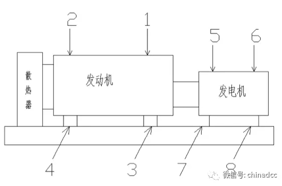
Figure 1 Diesel generator test points
(2) Measurement procedure
① The integrity of the unit under test meets the requirements of qualified products.
② Start and adjust the unit to measure under no-load and rated conditions.
③ Use a vibration meter to measure the vibration values of the unit in the horizontal, longitudinal, and vertical directions.
④ Use a table to record the relevant values.
The test results should meet the following requirements: engine single vibration amplitude <0.72mm; generator single vibration amplitude <0.32mm
14. Unit parallel operation (when required)
(1) Manual parallel operation:
① Start all units and parallel them at no load;
② After the no-load parallel operation is stable for 3 minutes, load each unit and distribute active power and reactive power evenly;
③ Disconnect and shut down one unit, and the other units should distribute the load of the unit evenly;
④ Disconnect and shut down the remaining units in turn until only one unit is left. During this period, the load should be transferred smoothly and the load of the shut down unit should be automatically distributed evenly (note that the load should be gradually reduced during this process to avoid overloading the unit);
⑤ Gradually reduce the load to 0, disconnect, cool and shut down the last unit.
(2) Automatic parallel connection:
① Set all units to automatic state and control the start of the units through external input signals;
② Start all units and connect them in parallel without load;
③ Load the units after stable operation;
④ The units enter the power management mode. When the load is less than 20% (adjustable) of the power of the online units, the unit with the lowest priority will be unloaded and shut down; similarly, when the load is greater than 80% (settable parameters) of the power of the online units, the non-operating generator sets with high priority will be automatically started after a delay. After the units start stably, they will automatically close synchronously to achieve soft loading and automatic load distribution with the online generator sets.
(3) Technical requirements:
During the whole process, the active and reactive power distribution deviation between the units shall be ≤±10%, and the load transfer between the units shall be smooth.
15. System monitoring function (when required)
The monitoring touch screen of the generator system should be able to display the single-line diagram of the generator system and the status of each circuit breaker, the electrical parameters of each unit operation, and can start, stop, close, open and other operations on each unit through the touch screen.
IV. Summary
The implementation of the acceptance of diesel generator sets is of great significance for the safe and stable operation and reliable power supply of diesel generator sets, and to maximize the role of diesel generator sets in data centers.


 English

