Correct installation, commissioning and use are the basis for ensuring the long-term safe, reliable and stable operation of diesel generator sets. Whether the installation, commissioning and use of the unit are standardized has a great impact on the operation, overhaul interval and service life of the unit. Whether the superior characteristics, service life and reliability of the unit can be brought into play during use depends to a certain extent on whether the installation, commissioning and use methods are correct.
1. Preparation before installation of standby generator sets
1. Transportation of the unit
When transporting, pay attention to tying the lifting rope in the appropriate position and lift and place it gently. When the unit is transported to the destination, it should be placed in the warehouse as much as possible. If there is no warehouse and it needs to be stored in the open air, the fuel tank should be padded to prevent rain from soaking, and a rainproof tent should be added to the box to prevent damage to the equipment by sun and rain.
Due to the large size and heavy weight of the unit, the transportation route should be arranged before installation, and a transportation port should be reserved in the machine room. If the doors and windows are not large enough, a larger transportation port can be reserved using the door and window positions. After the unit is moved in, the wall can be repaired and the doors and windows can be installed.
2. Unpacking
Before unpacking, you should first remove the dust and check whether the box is damaged. Verify the box number and quantity, and do not damage the machine when unpacking. The order of unpacking is to remove the top plate first, then the side plate. After unpacking, you should do the following:
①Count all units and accessories according to the unit list and packing list;
②Check whether the main dimensions of the unit and accessories are consistent with the drawings;
③Check whether the unit and accessories are damaged and rusted;
④If the unit cannot be installed in time after inspection, the disassembled parts should be re-applied with anti-rust oil on the finished surface for proper protection. Do not rotate the transmission and sliding parts of the unit before the anti-rust oil is removed. If the anti-rust oil has been removed after inspection, re-apply anti-rust oil after inspection;
⑤After unpacking, the unit should be kept carefully and must be placed horizontally. The flanges and various interfaces must be covered and wrapped to prevent rain and dust from entering.
3. Marking and positioning
According to the relationship dimensions between the unit and the center of the wall or column, and between the units marked on the unit layout plan, mark the vertical and horizontal reference lines of the unit installation site. The allowable deviation between the center of the unit and the center of the wall or column is 20mm, and the allowable deviation between the units is 10mm.
4. Check the equipment and prepare for installation
Check the equipment, understand the design content and construction drawings, prepare the materials required according to the design drawings, and send the materials to the construction site in sequence according to the construction plan.
If there are no design drawings, refer to the manual, and determine the size and location of the civil engineering plane according to the purpose and installation requirements of the equipment, while considering the water source, power supply, maintenance and use, and draw the unit layout plan.
5. Prepare lifting equipment and installation tools
II. Inspection before installation
Before installing the unit, first verify whether the machine room, foundation, etc. meet the requirements. Avoid the passive situation where the test machine or operation does not meet the requirements after the installation is implemented.
In terms of overall layout, the room design requirements can be based on the room and infrastructure conditions. The following factors should be considered when choosing a room:
① The surrounding environment is conducive to ventilation and exhaust, ensuring exhaust back pressure and avoiding warm air reflux.
② Sufficient operation and maintenance space.
③ Reasonable layout. The air inlet area is ≥ 2 times the area of the heat sink, and the air outlet area is ≥ 1.5 times the area of the heat sink.
④ Flammable and explosive items cannot be placed.
The room must have enough space for air to circulate freely, which is very important for ensuring the normal performance of the unit, reducing the power loss of the unit and ensuring the normal service life of the unit.
Other flammable and explosive items should not be placed inside the room, and any objects that are easily drawn into the protective net cover of the unit or even directly sucked into the body and may affect the normal use of the unit should not be placed inside the room.
For the installation and construction of units that generally do not have special requirements, the design requirements for the machine room are not high. It is only necessary to ensure that the air inlet and outlet of the machine room meet the requirements of the technical specifications and avoid warm air backflow under the premise of ensuring that the exhaust back pressure does not exceed the specified value, and sufficient operation and maintenance space can be reserved inside the machine room.
For some spare fuel tanks that need to be made and placed inside the machine room, attention should be paid to isolating them from the main space of the machine room and meeting the requirements of the local environmental protection and fire protection departments.
The machine room should be able to arrange sufficient air inlets and outlets. If the cooling capacity of the air inlet and outlet is insufficient, it is necessary to increase the air inlet and outlet fans or adopt the installation method of remote water tanks. When choosing the specific placement of the diesel generator set in the machine room, priority should be given to reserving sufficient operation and maintenance space and air circulation space around and on the upper part of the unit.
When the fully automatic load transfer system ATS or synchronous paralleling system is installed in the machine room, attention should be paid to reserving sufficient operation and maintenance space around it.
III. Unit Installation
1. Measure the vertical and horizontal center lines of the foundation and the unit. Before the unit is in place, find the vertical and horizontal center lines of the foundation and the unit and the installation positioning line according to the "laying out" on the drawing.
2. Hoist the unit. When hoisting, use a steel wire rope of sufficient strength at the lifting position of the unit (do not put it on the shaft to damage the oil pipe and meter box), lift the unit according to the technical installation regulations for hoisting, align it with the center line of the foundation and the installation hole, hoist the unit and level it. If the crane operation is not allowed on site, the unit can be placed on the rolling bar, rolled to the selected position, and then the unit can be lifted with a jack.
3. Leveling the unit. When installing, the level must be measured with a level ruler to fix the unit on a horizontal foundation. There should be a special shock-proof pad or anchor bolts between the unit and the foundation (only applicable to external shock absorbers).
Material list for installing the shock absorber under the machine base:
Installation base plate
Connecting angle steel
Riveting bolts
Rubber shock absorber
Angle steel connecting bolts
Shock absorber connecting bolts
Shock absorber adjustment
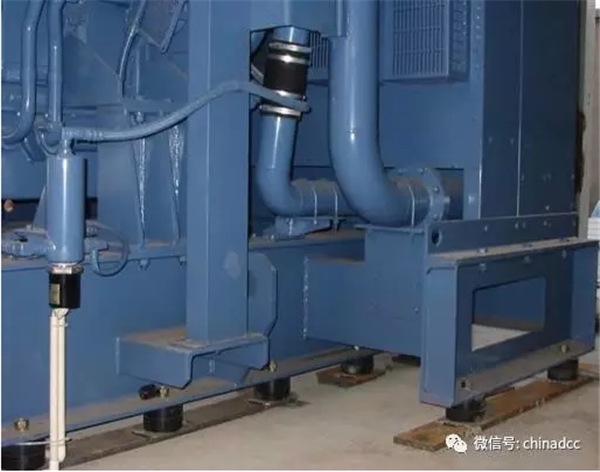
Figure 1 Note: Grounding treatment
After the unit is installed in place, it must be reliably grounded. The grounding is generally welded to the flat steel and the grounding point of the machine room to the side of the unit base and reliably connected to the grounding point (net). And comply with safety regulations.
IV. Fuel supply system
1. Fuel
The composition of fuel has a very important influence on the operation and service life of diesel engines and the composition of emissions. In order to obtain the specified power, fuel economy and meet the emission standards specified by the local environmental protection department, clean light fuel that meets international and national standards should be used. Most fuel will deteriorate and deposit if not used for a long time. For spare units, it is best to reserve only enough fuel for the unit to run continuously for a few hours. Therefore, the correct unit maintenance is to completely clean the fuel tank once every 18 months.
2. Fuel tank
The fuel tank capacity should be designed according to the full-load fuel consumption of the unit. When customers make fuel tanks, they should pay attention to the following aspects:
(1) The fuel discharge port should be located at the bottom of the fuel tank to facilitate the discharge of water and sediment and keep the fuel clean. The fuel tank outlet (inlet body) should be at least 50mm away from the bottom of the fuel tank to ensure that the fuel entering the body is clean enough to prevent water or other impurities from entering the combustion chamber.
(2) The distance between the oil outlet and the oil return port is at least 300mm. This is to prevent the hot oil and air in the oil return pipe from directly entering the oil outlet and the diesel engine, reducing the combustion efficiency and being detrimental to the normal working state and service life of the diesel engine. The oil suction port should not be lower than the oil pump by 1000mm, or the oil return pipe should not be higher than the oil pump by 2500mm (different for different diesel engines), so as to avoid excessive pressure difference, which will affect the normal operation of the oil pump and the normal supply of fuel.
An additional oil pan with a slight inclination should be added to the bottom of the fuel tank to collect the overflowed or leaked diesel.
There should be a vent pipe on the top of the fuel tank to release the polluted gas in the fuel tank and balance the atmospheric pressure in time.
The fuel tank is best made of steel plate. In order to avoid chemical reaction between fuel and fuel tank materials, produce impurities and deteriorate fuel quality, do not paint or galvanize the inside of the fuel tank. Copper plate and galvanized plate are not suitable as materials for making fuel tanks.
The size of the fuel tank should generally depend on the length of working time and the requirements of the local fire department. If the fuel tank is placed in the machine room, it needs to be isolated by a wall and a fire door should be installed.
The calculation of fuel tank capacity is as follows:
Fuel tank capacity (L) = engine rated power (KW) × engine fuel consumption rate × (L/KWh.) × fuel supply cycle (h) × 1.2
3. Fuel pipe installation
The fuel pipe should be a black iron seamless steel pipe instead of a galvanized pipe. The direction of the fuel pipe should avoid excessive influence of engine heat dissipation as much as possible. The maximum allowable temperature of the fuel before the injection pump is 60℃~70℃, depending on the model. It is recommended to use a soft connection between the engine and the fuel pipe, and ensure that the fuel pipe between the engine and the fuel tank will not leak.
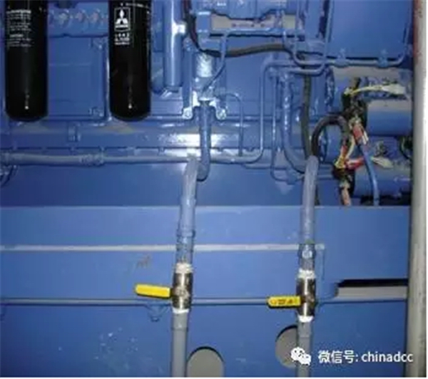
Figure 2 Oil pipeline and flexible connection
Figure 3 Laying of oil pipeline
4. Typical oil supply system
The oil supply system is generally composed of oil storage tank, daily oil tank, oil pump and solenoid valve, and connecting pipeline. When the oil storage tank is low (lower than the unit oil pump suction range) or high (higher than the pressure that the throttle can withstand), the daily oil tank must be used. There is a liquid level display and a float switch (automatic oil supply tank equipment) on the daily oil tank. The installation requirements of the oil pump system refer to the installation specifications of the equipment of this system.
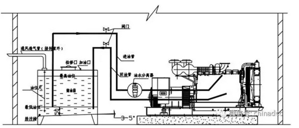
Figure 4 Schematic diagram of a typical fuel supply system
V. Installation of the exhaust system
1. The exhaust gas and smoke discharged during the operation of the unit must be directly led to the outdoors by a properly designed and installed exhaust system without affecting the surrounding environment and the normal work and life of residents. The exhaust system of the diesel generator set includes the muffler, bellows, flanges, elbows, gaskets and exhaust pipes connected from the machine room to the outside of the machine room that are standardly configured with the engine.
The exhaust system should minimize the number of elbows and shorten the total length of the exhaust pipe as much as possible, otherwise, the exhaust back pressure of the unit will increase, causing excessive power loss of the unit, affecting the normal operation of the unit and reducing the normal service life of the unit. The exhaust pipe diameter specified in the technical data of diesel generator sets is generally based on the installation example of a total exhaust pipe length of 6m and a maximum of one elbow and one muffler. When the exhaust system is actually installed, it has exceeded the specified length and the number of elbows, and the exhaust pipe diameter should be appropriately increased. The increase depends on the total length of the exhaust pipe and the number of elbows.
The first section of the pipe connected from the exhaust main pipe of the unit turbocharger must include a flexible bellows section, which has been randomly provided to the customer. The second section of the exhaust pipe should be elastically supported to avoid unreasonable installation of the exhaust pipe or additional lateral stress and compressive stress caused by relative displacement of the exhaust system due to thermal effects during the operation of the unit. All supporting mechanisms and suspension devices of the exhaust pipe should have a certain degree of elasticity.
When there is more than one unit in the machine room, remember that the exhaust system of each unit should be designed and installed independently. It is not allowed to let different units share the same exhaust pipe to avoid abnormal movement caused by different exhaust pressures of different units during operation, increase exhaust back pressure and prevent waste smoke and exhaust gas from flowing back through the shared pipe, affecting the normal power output of the unit and even causing damage to the unit.
2. Weld the random flange to the exhaust pipe (the length and number of exhaust pipes depend on the size of the machine room and the direction of exhaust), and pay attention to the matching relationship between the flanges during welding;
3. Configure the corresponding ferrules according to the size and installation height of the muffler and exhaust pipe;
4. Bolt the muffler, elbow, vertical exhaust pipe, and bellows according to the drawings to ensure good sealing everywhere;
5. Bolt the horizontal exhaust pipe to the muffler outlet to ensure the sealing of the joint surface;
6. Wrap a layer of insulation material around the exhaust pipe; to avoid excessive temperature in the machine room, deteriorate the normal working environment of the unit and cause burns to the operator, and reduce the mechanical noise of the exhaust system and supercharger of the unit, the exhaust system in the machine room should be effectively insulated and soundproofed.
When the outer surface temperature of the exhaust pipe is ≤450℃, the insulation layer uses a layer of rock wool felt (rock wool is generally used for the insulation part with a temperature of 600℃). When the temperature of the outer surface of the exhaust pipe is ≥500℃, the insulation layer adopts two layers. That is, the layer in contact with the pipe wall is aluminum silicate fiber felt, and the outer layer is rock wool felt.
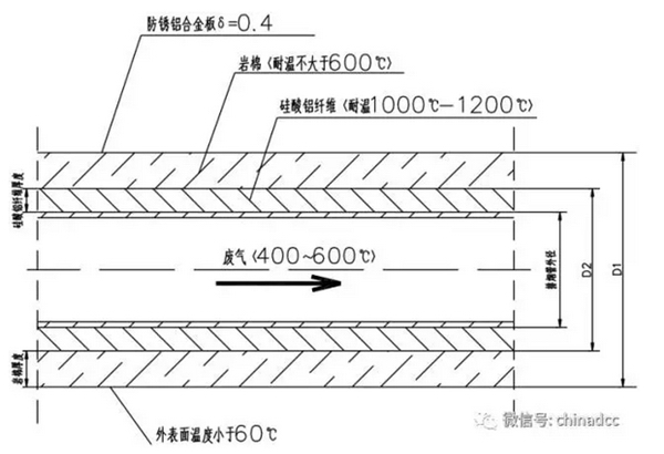
Figure 5 Muffler and exhaust pipe insulation cross-section
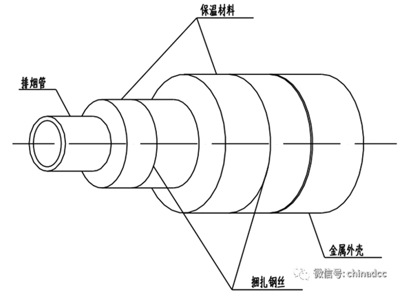
Figure 6 Muffler and exhaust pipe insulation stereogram
7. The connection between the diesel generator set and the exhaust pipe is usually made of corrugated pipe. The weight of all exhaust pipes is not allowed to press on the corrugated pipe, and the corrugated pipe should be kept free.
8. The outermost outlet of the exhaust pipe should be treated to prevent rainwater, such as cutting a suitable angle under the pipe mouth or installing a rain cap.
9. When the exhaust pipe needs to pass through the wall, a flexible expansion sleeve should be installed. Otherwise, the exhaust pipe will cause lateral stress and pressure due to the thermal expansion and contraction effect, affecting the stability of the exhaust system of the unit and accelerating the abnormal loss of the exhaust system and supercharging system of the unit, and causing cracks in the wall due to long-term stress.
The exhaust duct and muffler should be supported separately and should not be directly supported on the diesel engine exhaust main pipe or fixed on other parts of the diesel engine. See the following figure for specific vibration isolation installation:
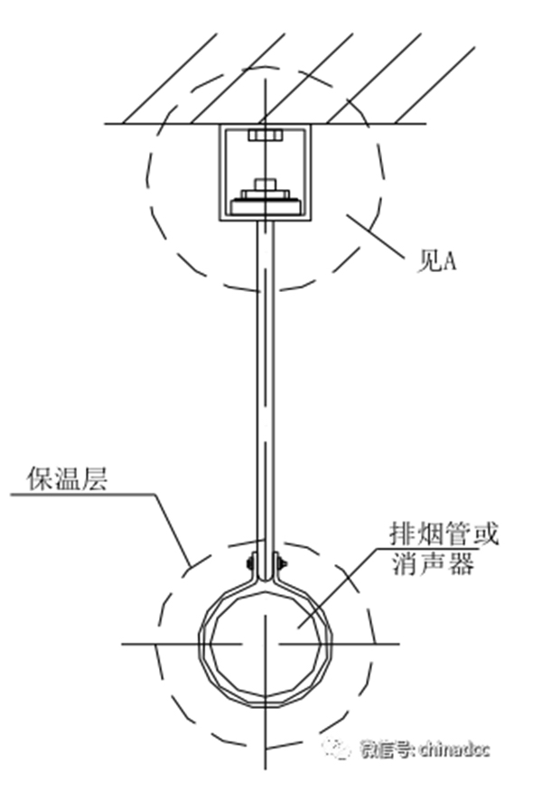
Figure 7 Muffler and exhaust pipe vibration isolation installation diagram
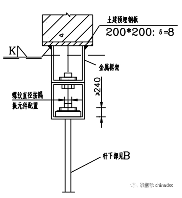
Figure 8 A—Beam bottom embedded plate installation
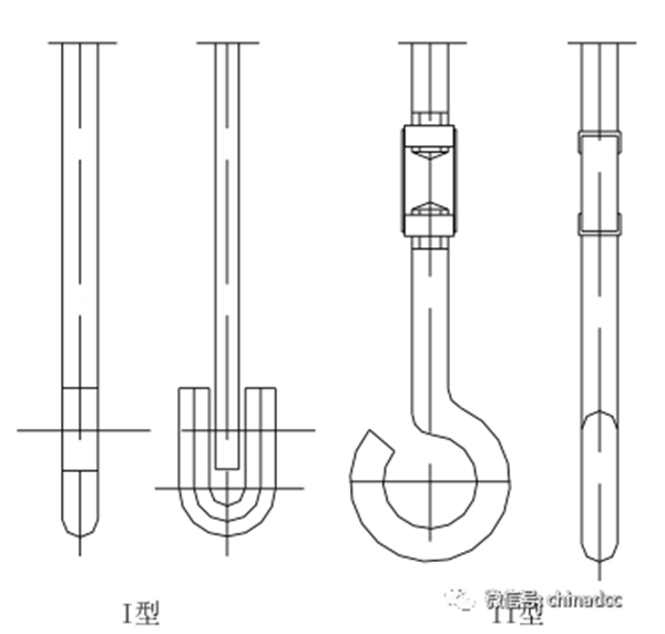
Figure 9 B—Hook
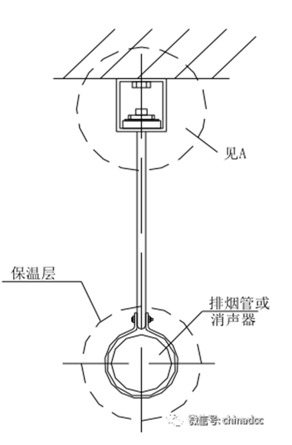
Figure 10 Muffler and exhaust pipe vibration isolation installation diagram
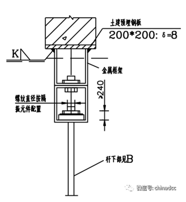
Figure 11 A—Installation of embedded plate at bottom of beam
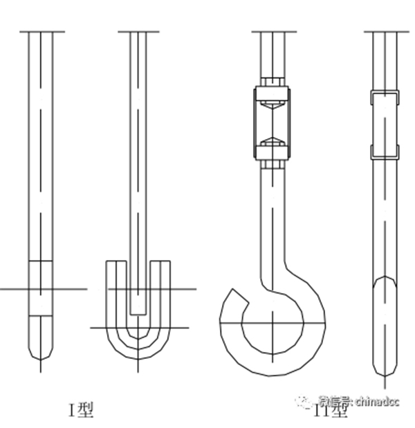
Figure 12 B—Hook
VI. Ventilation System
When the diesel generator set is running, on the one hand, some fresh air will be sucked into the combustion chamber, so that it is evenly mixed with the fuel and burned in the combustion chamber to drive the entire unit to operate continuously; at the same time, the large amount of heat generated by the unit during operation must be dissipated out of the machine room in time, which will consume a lot of cool air. Therefore, in addition to the standard unit itself must have a good circulating water cooling or oil cooling structure, the cooling and ventilation system of the machine room is also very important and indispensable. It must be ensured that there is enough air flowing through the machine room to supplement the air consumed by the engine combustion and to discharge the large amount of heat dissipated during the operation of the unit out of the machine room through the radiator core, so that the temperature in the machine room is as close to the ambient temperature as possible and the body temperature is kept within the normal working range. When the machine room conditions cannot meet the net area requirements of the air inlet and outlet specified in this manual, it must be considered to use forced air inlet and outlet to ensure the normal combustion and cooling needs of the unit.
In buildings, vents are usually equipped with shutters and metal protective mesh curtains. In winter, The machine room should always maintain an appropriate temperature to avoid affecting the normal starting ability of the unit or causing the cooling water to freeze and damage the unit. This requires that all ventilation openings in the machine room must be adjustable so that they can be closed automatically or manually when the unit is out of use. At the same time, it is recommended that the unit be equipped with a matching water jacket heater and keep it in normal working condition at all times.
1. Air inlet
The air inlet should be located in a reasonable position with the lowest dust concentration possible and ensure that there are no foreign objects nearby. When conditions permit, it is recommended that customers use an inclined position close to the generator end. The upper air intake mode is equipped with shutters and metal protective curtains to prevent foreign objects from entering and ensure normal air convection. To prevent hot air backflow, the unit air inlet should be as far away from the exhaust port as possible, and the air in the machine room should be allowed to flow directly as much as possible. The air inlet should be protected to prevent rain and other foreign objects from entering. For conventional closed-loop water-cooled diesel generator sets, the net flow area of the air inlet is estimated to be no less than 1.5 to 1.8 times the windward area of the radiator.
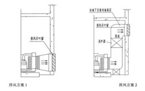
The following machine room air intake plan can be used for reference:
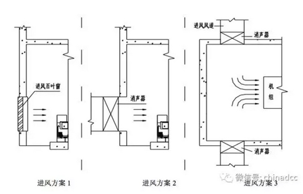
Figure 13 Reference air intake plan for the machine room
2. Exhaust vent
The net flow area of the exhaust vent is greater than 1.25 to 1.5 times the windward area of the radiator. The center position of the exhaust vent should be consistent with the center position of the unit radiator core as much as possible, and the width-to-height ratio of the exhaust vent should also be the same as the width-to-height ratio of the radiator core as much as possible. In order to prevent hot air from flowing back and mechanical vibration from being transmitted outward, it is recommended to install an elastic shock-absorbing trumpet-type air guide slot between the radiator and the exhaust vent.
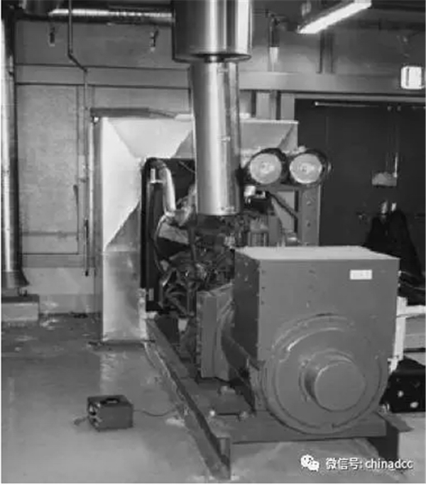
Figure 14 Elastic shock-absorbing trumpet-type air guide slot 1
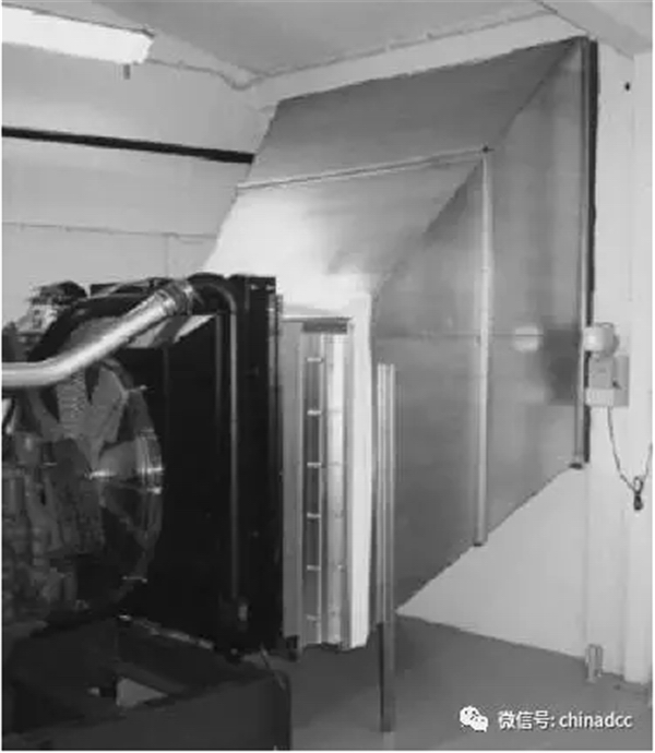
Figure 15 Elastic shock-absorbing trumpet-type air duct 2
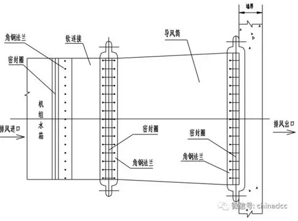
Figure 16 Elastic shock-absorbing trumpet-type air duct large-scale drawing
The elastic shock-absorbing trumpet-type air duct is shown in Figure 16 and is divided into two parts: the soft connection part uses heat-insulating canvas, one end of which is connected to the end face of the unit water tank through an angle iron flange, and the other end is also connected to the air duct through an angle iron flange; the air duct uses a galvanized sheet and angle iron frame structure, and one end is connected to the exhaust louver through an angle iron flange. The connections between the various components of the exhaust duct are all connected with bolts, and the iron parts of the exhaust duct must first be painted with anti-rust paint twice, and then painted with the same color as the unit. Rubber sealing rings should be placed between the angle iron flanges to prevent hot air leakage.
Installation of ventilation system
Bury the exhaust iron frame into the wall, secure it with cement, and assemble it after it dries;
Install the inlet and outlet louvers or air valves and fix them with bolts;
If you need to install inlet and outlet fans, intermediate transition bodies, flexible connections, exhaust vents, and related process standards, please refer to the relevant professionals.
Figure 17
List of exhaust hood and soft connection materials:
Angle steel frame
Galvanized steel plate (δ=1)
Flat iron strip (δ=2)
Thick canvas strip (W=300-500)
Aluminum rivets and other auxiliary materials
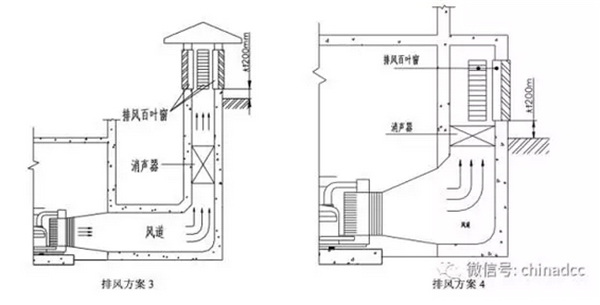
The following machine room exhaust scheme can be used for reference:
3. Air circulation
A good machine room ventilation system must ensure that there is enough air flowing in and out, and that it can circulate freely in the machine room. Therefore, there should be enough space in the machine room to ensure that the temperature in the machine room remains balanced and the air circulates normally and smoothly. If there are no restrictions on special installation conditions, the ventilation system should usually adopt a direct inlet and direct outlet type. And absolutely avoid the hot air discharged by the unit to enter the machine room again through the air inlet of the machine room.
VII. Cooling system
Diesel generator sets can be divided into the following three system cooling methods according to the customer's installation and use requirements:
Closed cycle fan water cooling
Split cooling system
Heat exchanger system
1. Closed cycle system
Except for special requirements, the standard configuration units are all equipped with a closed cycle cooling method with a water tank. In general, the cooling system includes two parts: the cooling water system and the cooling air system.
When the radiator is installed at the rear end of the engine, the unit should be positioned so that the radiator core is as close to the exhaust port as possible according to the above requirements (the maximum distance between the radiator core and the outlet is recommended to be 150mm). Otherwise, hot air backflow may occur.
If the unit cannot be positioned as described above, a canvas exhaust trough with a steel flange must be added to the system to connect the radiator and exhaust louver.
The elbow of the trough must have a perfect radius of curvature. If a long process pipeline is required, the cross-sectional area of the pipeline must be enlarged to reduce the back pressure of the radiator.
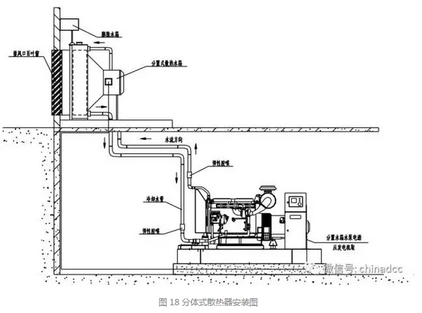
2. Split cooling system
When the unit is installed in the basement, the actual space is likely to limit the use of the trough. In this case, other cooling methods can generally be used.
The cooling system of the remote cooling water tank is one of the options available to customers. In this system, the radiator is separated from the unit and the electric fan is used for heat dissipation. This system can be used as a fully enclosed unit component for outdoor use or in an open form for indoor installation. To ensure the synchronization of the electric fan and the unit, it is recommended that the customer use the unit output power as the power supply for the electric fan.
When the radiator is installed above 3m or the horizontal distance exceeds 10m, most units require a separate water tank and electric water pump. The size of the separate water tank depends on the capacity of the entire cooling system, that is, the total amount of pipes required plus the cooling water consumption.
The cooling water is driven by an electric circulation pump and circulates from the separate water tank through the radiator and the unit. Generally, the radiator fan and water pump motor are powered by a generator, and the power they consume should be included in the unit output power. When the unit is inactive, water will flow from the radiator to the separate water tank. When the unit is running, this separate water tank must maintain enough cooling water for a long time to ensure that the entire cooling system is filled and the cooling water is effectively circulated. See Figure 18 Split Radiator Installation Diagram.
Points to note about this system:
(1) Prevent foreign impurities from contaminating the coolant;
(2) The turbulence of the separate water tank can cause the coolant to oxidize;
(3) Avoid air stagnation in the system, and the pipes should be equipped with vents;
(4) Perform appropriate water treatment to meet the unit's use requirements;
(5) Prevent coolant condensation;
(6) Ensure that the coolant maintains (pressure-free) natural flow in the engine body;
(7) If the radiator is installed at the same level as the engine, there is no need to use a separate water tank, but an expansion tank should be installed directly above the radiator to allow the cooling water to expand and replenish due to heat.
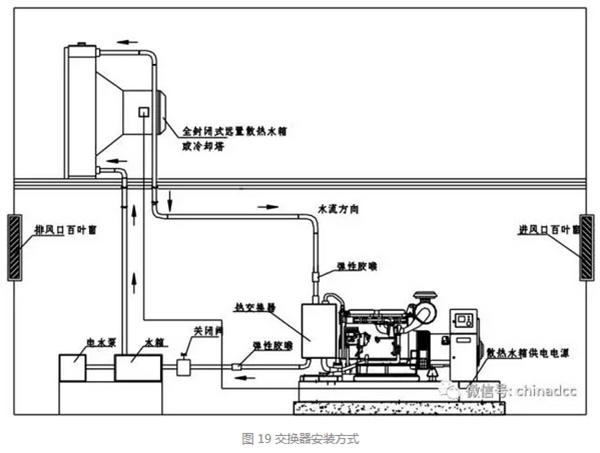
3. Heat exchanger system
Adopt heat exchanger cooling method. This method can be divided into two specific types: "standard heat exchanger cooling method" and "split water tank with heat exchanger cooling method". This system requires less space than the split water tank, and its closed water circuit can automatically replenish the cooling water lost by evaporation using the ball valve of the replenishment water tank to ensure that there is always enough cooling water in the cooling system.
Diesel generator sets can be equipped with heat exchangers according to special requirements of users. Heat exchangers can be used as cooling means for units in areas where water quality may be polluted or where cooling water can be provided from cooling towers or large water tanks. However, after passing through the heat exchanger, the water should be regarded as polluted water and cannot be used for domestic water.
Since the used water must flow to the wastewater pipe, drinking water is not allowed to be used for heat exchangers in most places. The water pressure of the heat exchanger can be maintained at about 0.14MPa.
When using a cooling system with a remote radiator or heat exchanger, the machine room must maintain a certain amount of ventilation to provide enough air for engine combustion, as well as for ventilation of the machine room and cooling the radiant heat emitted by the unit.
VIII. Installation of electrical system
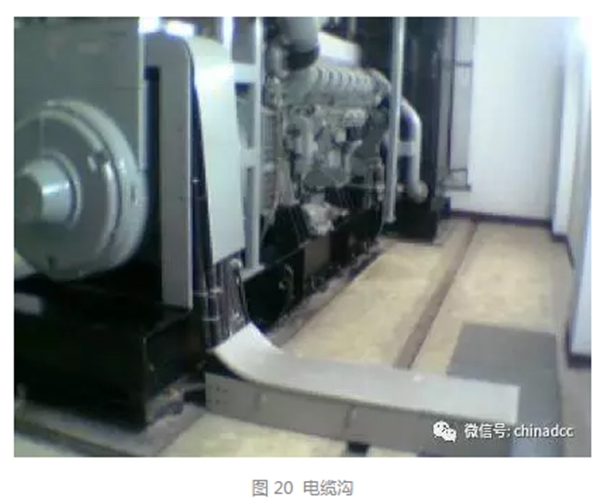
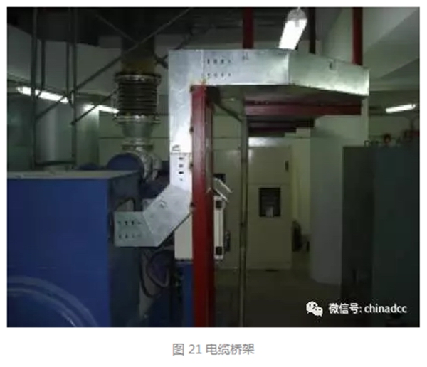
1. Cable laying methods
There are several ways to lay cables, such as direct burial, cable trenches and cable trays. The electrical connection must be in reliable contact to prevent loosening, twisting and insulation damage caused by vibration.
Cable area selection: The output cable of the generator set should not be too small. Please select a cable with a suitable cross-sectional area according to the rated current of the generator set and refer to the cable selection manual.
2. Selection of cable laying path
When selecting the cable laying path, the following principles should be considered:
The power path should be the shortest and the least bends;
The cable should be as little damaged as possible by mechanical, chemical and ground current factors;
The heat dissipation conditions should be good;
Try to avoid crossing with other pipelines;
Avoid places where digging is planned.
3. General requirements for cable laying
When laying cables, the planning and design requirements of relevant technical regulations must be followed.
Under the conditions of laying conditions, a margin of 1.5 to 2% can be considered for cable length as a spare for maintenance, and direct buried cables should be buried in a wavy shape.
For cables entering or leading out of buildings or structures, cables passing through floors and main walls, cables leading out from cable trenches to poles, or cables laid along walls, the section is 2m above the ground and 0.25m deep underground. The cable should be protected by a steel pipe, and the inner diameter of the steel pipe shall not be less than 2 times the outer diameter of the cable.
When the cable is buried in the first phase with different pipelines, it is not allowed to lay the cable in the trench where the gas pipe, natural gas pipe and liquid fuel pipeline are laid; a few cables are allowed to be laid in the open trench or tunnel of the water pipe or ventilation duct, or cross these trenches. In the open trench or tunnel of the thermal pipeline, cables are generally not laid; in special circumstances, if the cable will not be overheated, a few cables may be allowed to be laid in the trench of the thermal pipeline, but they should be separated on different sides, or the cables should be installed under the thermal pipeline.
The buried depth of the direct buried cable shall not be less than 0.7m, and the trench shall not be 0.6m away from the foundation of the building.
The structure of the cable trench should take into account the problems of fire prevention and waterproofing.
The metal sheath, metal cable head, protective steel pipe and metal bracket of the cable should all be reliably grounded.
For the sake of convenience and safety, it is recommended that customers pre-lay the cables in the cable trough and perform anti-penetration and anti-leakage treatment when connecting the units to the ATS Yao switchboard and the paralleling cabinet. The electrical connections must be in reliable contact to prevent loosening, twisting and insulation damage caused by vibration.


 English

